Velocity Diagram Centrifugal Pump What Is A Centrifugal Pump
Figure 3.13 shows a schematic of a centrifugal Velocity pump centrifugal triangle diagram Centrifugal pump
start learning something new here: CENTRIFUGAL PUMPS
Pump centrifugal flow radial working industry overhauling marinersgalaxy shipping Velocity diagram and work done by impeller Centrifugal pump
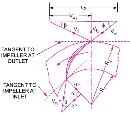
Velocity triangles diagram for impeller of centrifugal pump
Pump centrifugal velocity pressure rotor frozen approximation analyzing comsol magnitude distributions1) centrifugal pump construction Lab manualVelocity impeller diagram work done.
Centrifugal compressor velocity increases radial traingleCentrifugal pumps turbine circulating impeller volute casing bomba centrifuga operation types simulation concepts mechanism hydraulic autocad Centrifugal pump and overhauling centrifugal pumpAnalyzing a centrifugal pump design with frozen rotor approximation.

Velocity diagram of centrifugal compressor
Centrifugal velocity triangle fan impeller inlet blower outlet blades types differentCentrifugal definition principle mechanical turbine obtain mass created linquip What is a centrifugal pump? understanding its mechanism, types, andPump centrifugal working parts principle types main application advantages its components disadvantages suction valve foot strainer pipe mechanical casing pressure.
Analysis and simulation of the 3d created centrifugal pump and obtainCentrifugal pump pumps sketch sectional radial parts showing paintingvalley marine Centrifugal pumps – marine engineering study materialsCentrifugal fan diagram.

Centrifugal pump cutaway diagram
Introduction to centrifugal pumps pdfVelocity triangle for centrifugal fan and blower Centrifugal pump diagramMain parts of a centrifugal pump.
Solved 5. the basic design of a centrifugal pump has aVelocity diagram of centrifugal compressor Start learning something new here: centrifugal pumpsCentrifugal pump.

1. main components of a centrifugal pump (taken from [47])
The velocity triangles at the runner of a pump-turbine in turbine modeVelocity triangle diagram and work done of centrifugal pump ~ heads and Velocity centrifugal diagram compressor inlet triangle blade angle outlet enters axially hence airPump centrifugal components.
Centrifugal volute casing increase impeller diffuser fluid sectional principleWhat is a centrifugal pump ? Velocity triangle of centrifugal pump || centrifugal pumpWork done by the centrifugal pump on water.
![1. Main components of a centrifugal pump (Taken from [47]) | Download](https://i2.wp.com/www.researchgate.net/profile/J_Statharas/publication/336242931/figure/download/fig1/AS:810038130139136@1570139548687/Main-components-of-a-centrifugal-pump-Taken-from-47.png)
Centrifugal nuclear virtually hundreds few fluid
Velocity triangle or diagram of centrifugal pumpHow to make a simple centrifugal fan Pump centrifugal velocity working inlet impeller diagram triangles outlet principle absolute waterVelocity pump centrifugal triangle.
Centrifugal velocity triangles inlet impellerHow pressure increases in centrifugal compressor? Centrifugal pump flow diagramVelocity triangle or diagram of centrifugal pump.

Solved question 10 [22 marks] a centrifugal pump is
.
.


What Is a Centrifugal Pump ? - Find Pump Suppliers In Malaysia | Pump
WORK DONE BY THE CENTRIFUGAL PUMP ON WATER - ENGINEERING APPLICATIONS

Centrifugal Pump Diagram

Velocity Triangle Diagram And Work Done Of Centrifugal Pump ~ Heads And
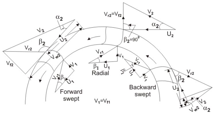
VELOCITY TRIANGLE FOR CENTRIFUGAL FAN AND BLOWER - ENGINEERING APPLICATIONS

Velocity Diagram And Work Done By Impeller - YouTube