Variable Speed Drive Schematic Diagram Basic Concept Of A Va
Principle of variable speed drive and schematic diagram General configuration of variable speed drive What is variable speed drive used for?
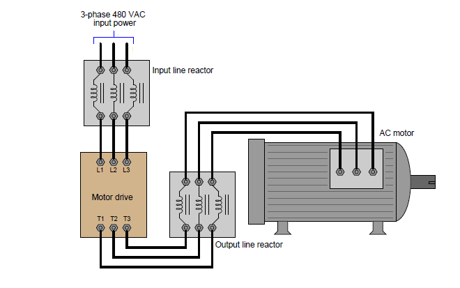
Figure 5-7a. Schematic Variations for Variable Speed Drives.
Industrial instrumentation and control: how a vfd works and when to use it Variable frequency drive Variable frequency drive motor ac components dc inverter control voltage bus principle working motors converter sections three figure main
What is variable frequency drive circuit: its operation, types and
What is variable speed drive?Wiring diagram for variable speed Variable logopaedie behrens drive versionSpeed configuration.
Variable speed drivesPrinciples of operation Variable drives ufcVariable vfd instrumentation.

How to build a variable speed drive
Schematic of the variable-speed drive applicationsVariable principle 19 variable speed drive structureVariable frequency drives explained.
Basic concept of a variable speed drive.Principle slideshare Variable speed driveVfd wiring diagram with motor, switches, and external devices.

Pump schematic with variable speed drive
Topology and typical circuit model of variable-speed drive.[diagram] electric motor wiring diagram rectifier How to repair any vfdVfd diagram wiring motor circuit ac drives operation panel drive variable frequency schematic principles dc pulse width inverter convert phase.
Variable vfd schematic drives pnnlVfd circuit diagram explanation Vfd controller for ac motorDrive variable frequency speed motor control ac principle working controls figure rpm.
Series on a variable speed drive
Electrical standards: variable frequency drive working principle andVariable topology typical Variable frequency driveTraditional variable speed drive system configuration..
Vfd control wiring diagramVariable speed drives improve machine efficiency in industrial Wiring diagram pressure vfd powerflex variable drive frequency constant supply water allen bradley acHow to build a variable speed drive.

Principle of variable speed drive and schematic diagram
Vfd frequency inverter induction braking works circuit speed converter electronicVariable principle What is a vfd?Vfd circuit drive types operation working gupta sourav jan.
Allen bradley vfd powerflex 753 wiring diagramVfd variable speed drive motor ac diagram installation frequency block terminals protection output switches off controlled function control circuit phase What is a variable frequency drive and its working principleFigure 5-7a. schematic variations for variable speed drives..


vfd circuit diagram explanation - Wiring Diagram and Schematics

Variable Speed Drives | PNNL

Principles of Operation - AC VFD Drives | Natural Resources Canada

Basic concept of a variable speed drive. | Download Scientific Diagram

Variable Speed Drives improve machine efficiency in Industrial

What is Variable Speed Drive used for?

PRINCIPLE OF VARIABLE SPEED DRIVE AND SCHEMATIC DIAGRAM